17000 (Maker Edge Pro) - Replacing the Control Panel
Introduction
Tools Required
Replacing the Control Panel.
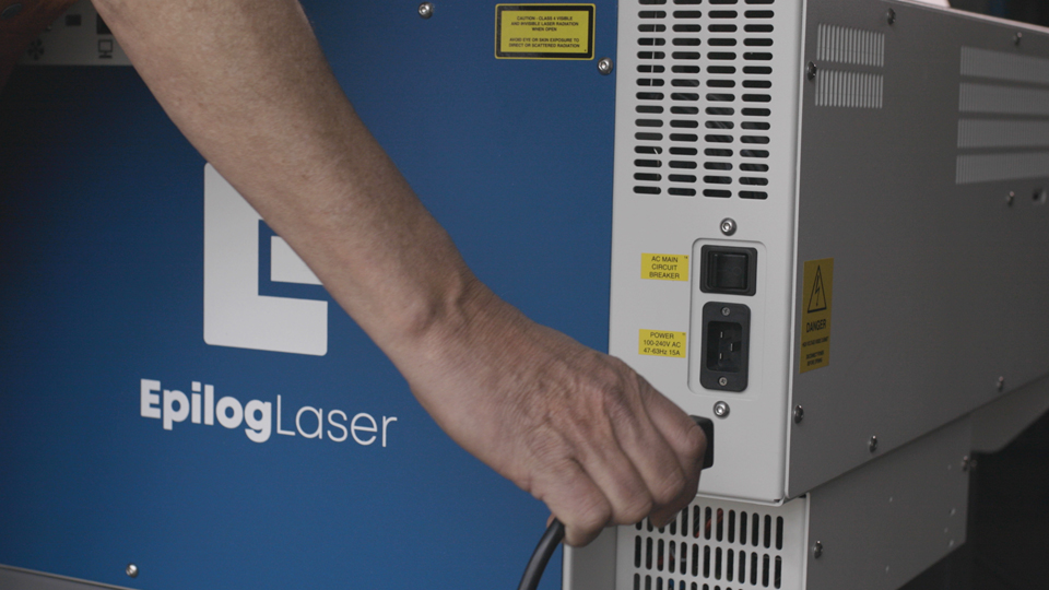
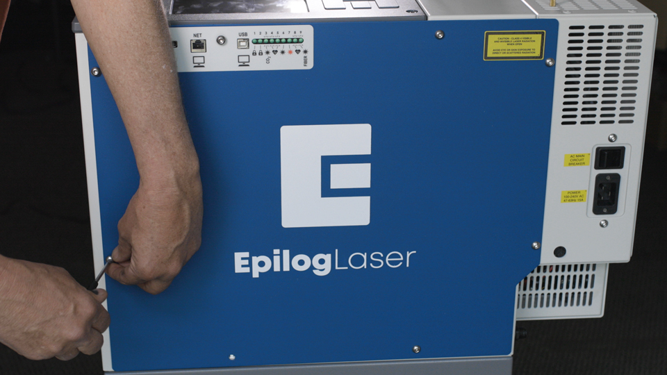
Turn off and unplug the machine.
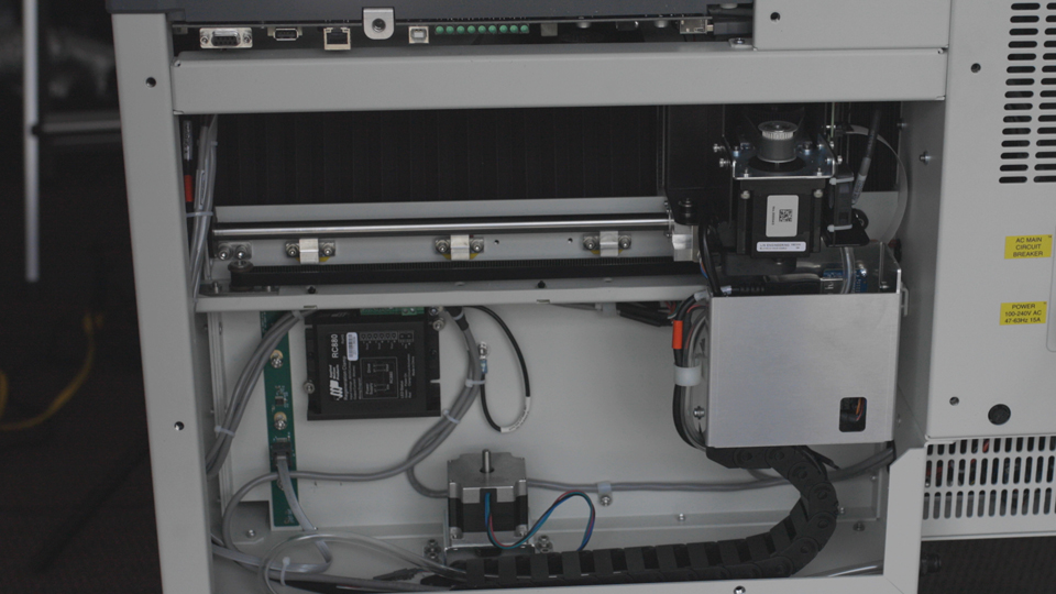
Remove Panel
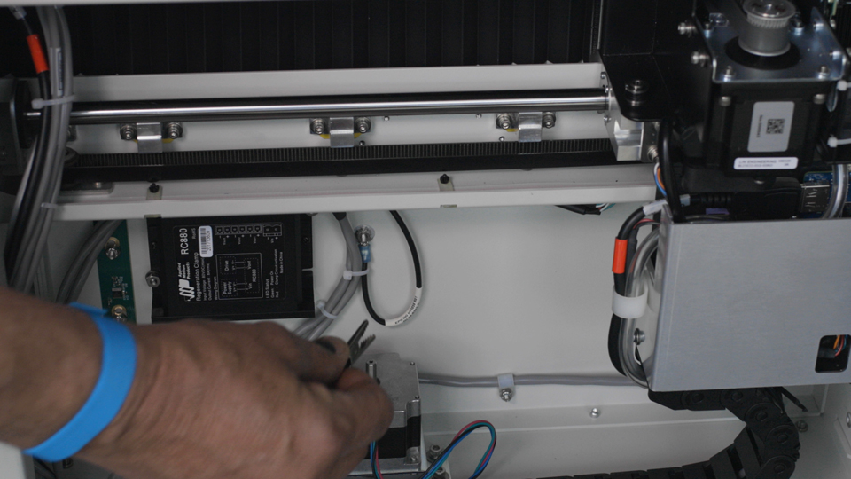
Using a 5/32″ Hex Key, remove the 8 screws that secure the right-hand side access panel and set them to the side.
Remove Old Keypad
Open the display panel package you received and put on the anti-static strap. Clip the strap on to any metal part of the machine. Always wear the anti-static strap when handling the control board to avoid damaging the unit through static discharge.
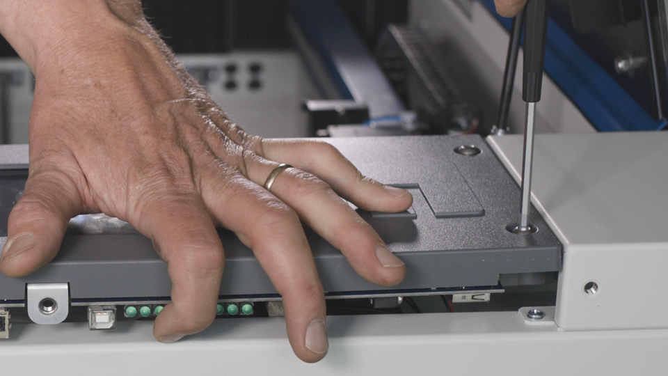
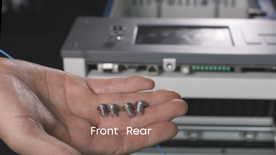
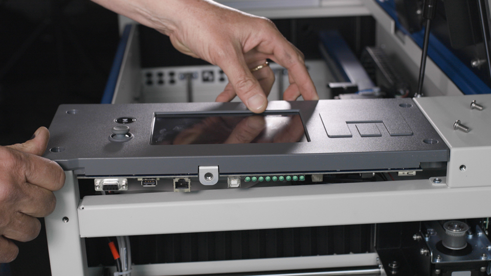
Remove the 4 screws that secure the control panel to the machine’s chassis. Note: The two Allen screws used in the rear of the control assembly are longer than the ones used in the front. These need to be re-installed in the same location.
Gently lift the front of the display and pull it towards you while rotating the front of the control panel up.
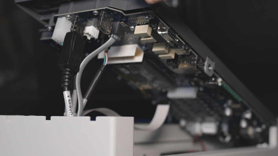
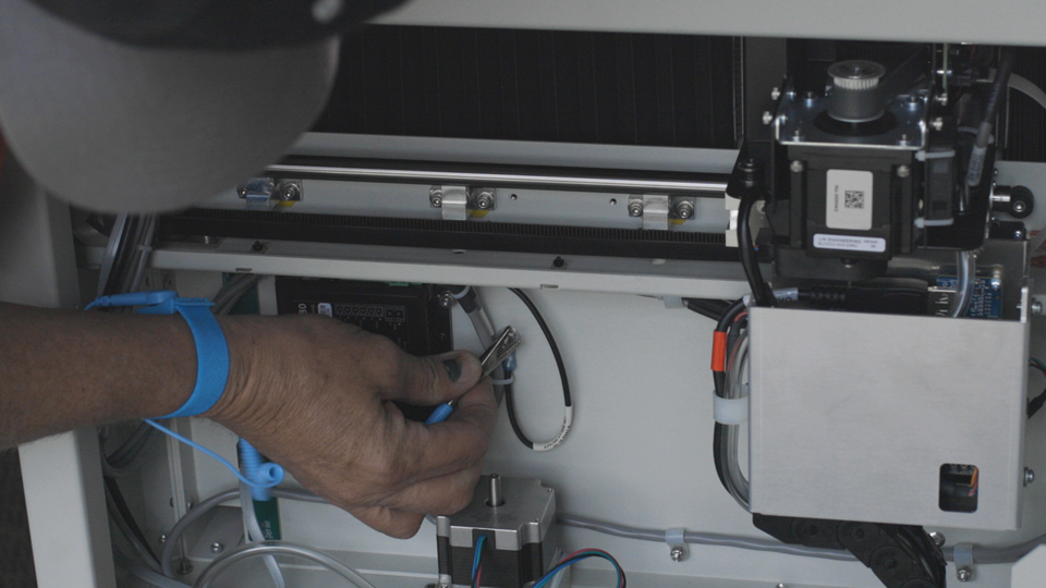
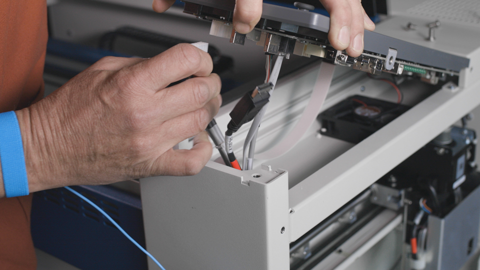
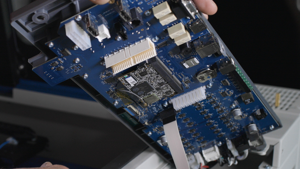
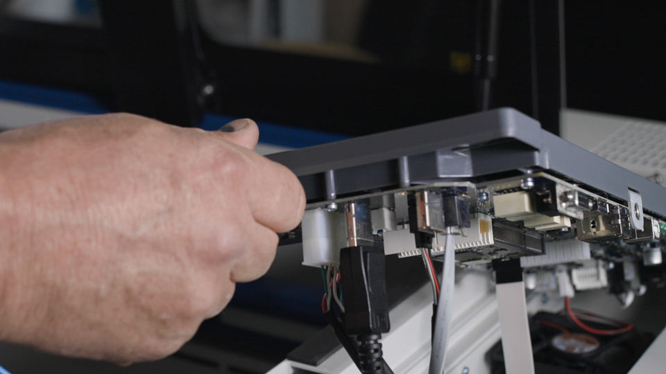
There are a total of 12 connections that need to be disconnected from the control panel assembly before it can be removed.
- 4 in the front
- 1 in the center
- 7 at the rear
There are two that need you need to pay close attention to.
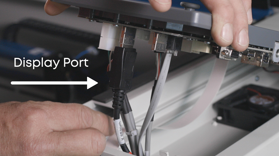
The display port connection is at the front of the control panel assembly. The display cable needs to be reconnected to the one it was removed from.
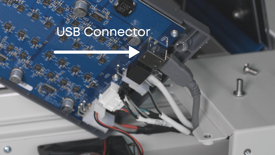
The USB connector is at the rear of the control panel assembly. There are two ports built into a single socket. Note which one the cable is connected to, it will need to be reinstalled in to the same one.
The remainder are unique and will only connect in to one location on the board.
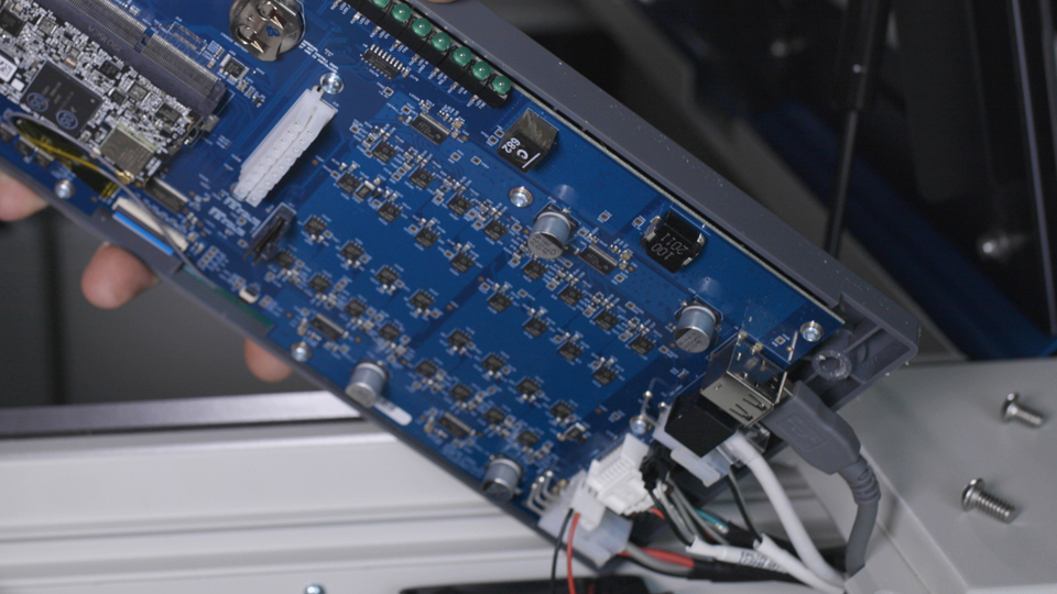
Once the electrical connectors are de-mated, set the old control assembly to one side.
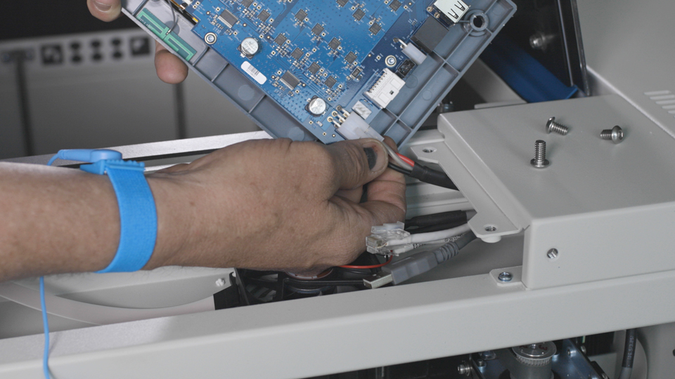
Turn the control panel on its back on a soft surface.
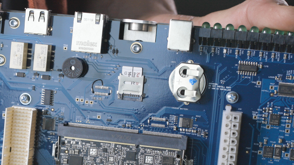
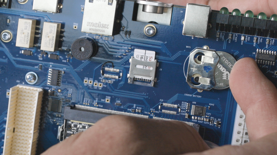
Locate the SD card slot on the board.
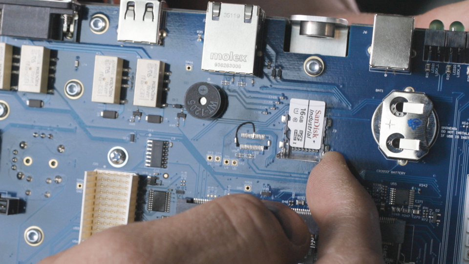
Remove the SD card and set it to the side.
Once you have your new control board, install the SD card printed side up into the SD card slot.
Turn the control panel on its back on a soft surface.
Locate the coin battery and remove it.
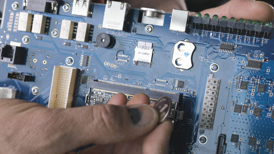
Install the new coin battery in its place.
Install New Keypad
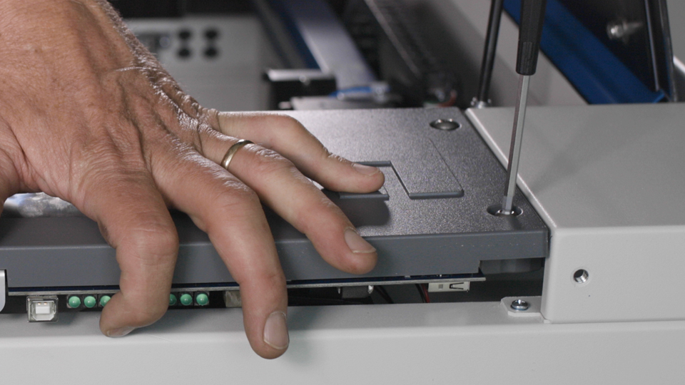
Position the replacement control assembly over engravers chassis, with the rear much lower than the front.

Connect the 7 electrical connections along the rear of the control panel paying close attention to the slot the USB connection is installed in.
Connect the Flex cable to the center port on the control panel assembly.
Connect the 4 remaining connectors to the electrical connections at the front of the control panel assembly, paying close attention to the Display cable port. Ensure that it is reconnected to the correct display port connection on the board.

Lower the control assembly so that it rests on the machine chassis.
Align the control assembly mounting holes with the holes in the chassis.
Install the 2 longer screws in the rear mounting holes of the control assembly.
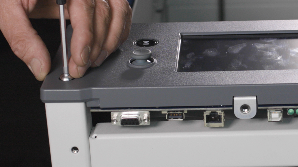
Install the 2 shorter screws in the front mounting holes of the control assembly.
Remove the anti-static strap and disconnect it from the machine.
Reinstall Panel
Install the right-hand side panel using the 8 screws that were removed earlier.
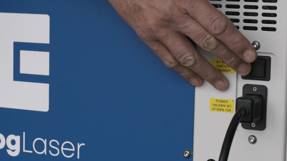
Plug in the machine and turn the power on.
Once the machine has fully booted up, set up the network, IP, Subnet and Gateway settings.
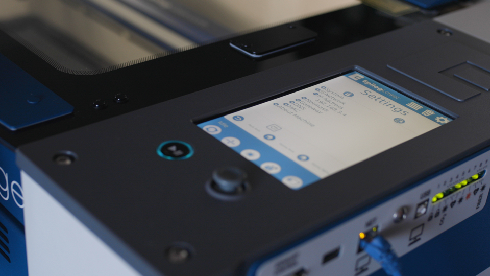
Reconnect the USB or Ethernet cable used previously to send jobs to your machine.

Related Articles
17000 (Maker Edge Pro) - CO2 Laser No Outuput Checklist
This document is designed to help determine if you need to replace your laser tube. Overview These items should be checked before replacing a CO2 laser tube with no output. If the laser has been inactive for more than one (1) month, follow the ...17000 (Maker Edge Pro) - CO2 Laser Alignment
Introduction In this article we’ll walk you through aligning the laser on the Epilog Fusion Edge & Fusion Pro. During this procedure, all persons present in the room must be equipped with eye protection, such as safety glasses, eyeglasses or goggles. ...17000 (Maker Edge Pro) - X-Axis Belt Tensioning Guide
Instructions on tensioning the X-Axis belt on a 17000 Edge, Maker, Pro, or 16000 Pro 48 200 Watt. Overview This document and video provide instructions on utilizing the X-Axis belt tensioning tool. The tool assesses the belt's tightness, allowing us ...17000 (Maker Edge Pro) - CO2 Laser Low Output Checklist
Overview Having to continually reduce speed and increase power can indicate low output from the laser. This document will help identify a low output laser tube on a 17000 Maker, Edge, or Pro machine. There is a PDF version of this document on the ...17000 (Maker Edge Pro) - Updating the Firmware
Firmware update procedure for the Fusion Maker, Edge, Pro, and Galvo. Find the newest version of the firmware for your engraver by clicking HERE. Overview In firmware version 1.0.9.0, the update process has been streamlined. For systems operating on ...