14000 - Fusion M2 Laser Alignment
Introduction
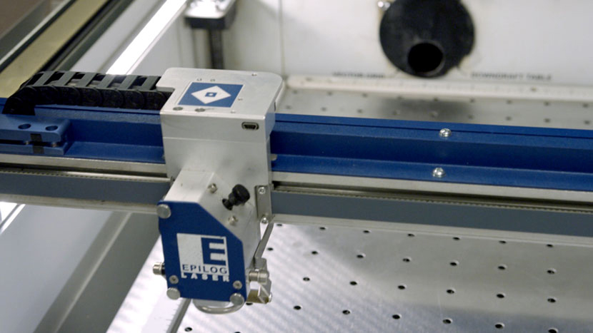
In this article we’ll walk through aligning the Epilog Fusion M2’s laser.

Tools Required
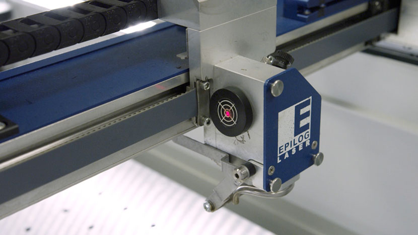
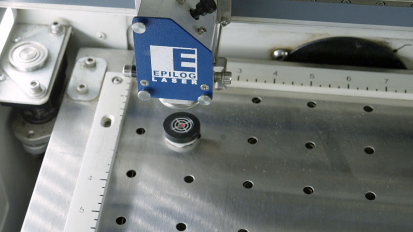
Alignment Target
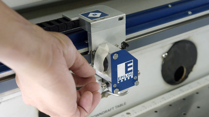
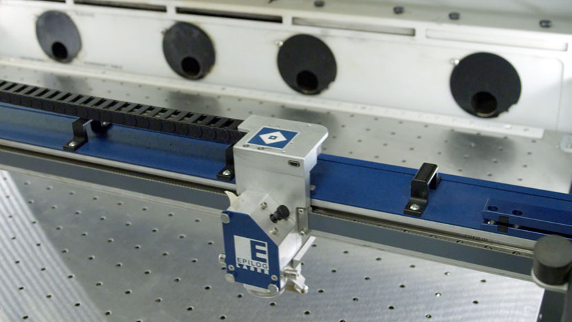
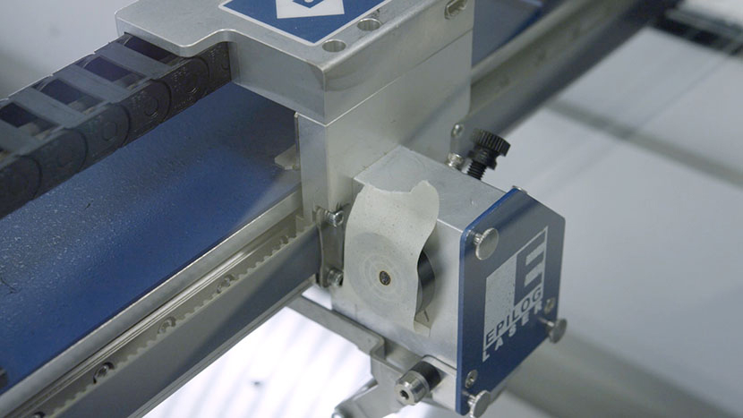
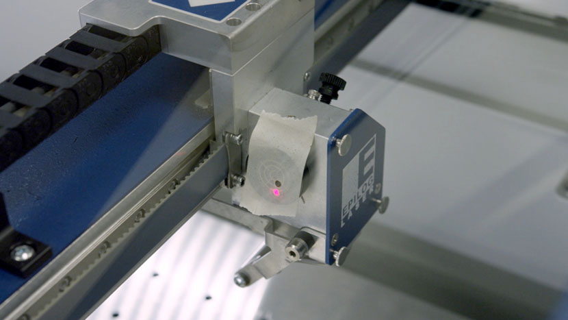
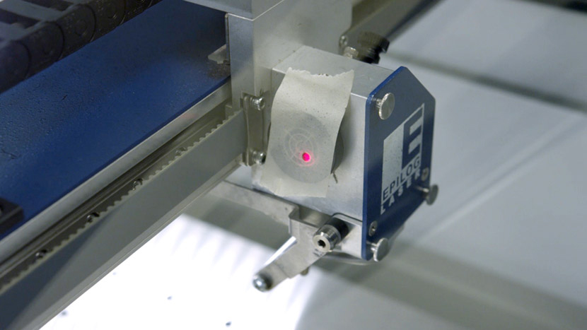
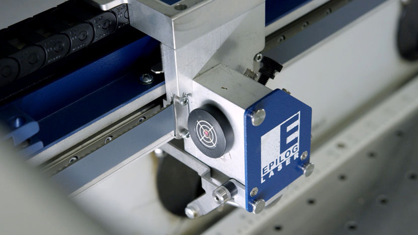
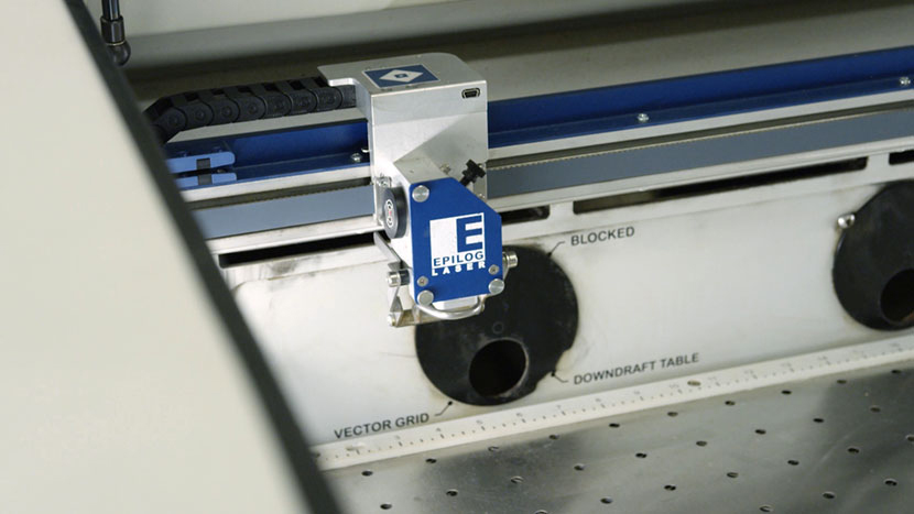
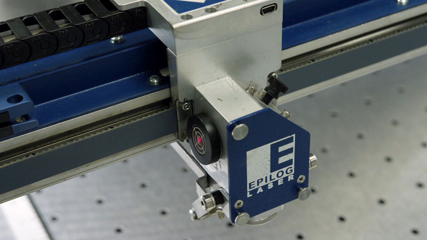
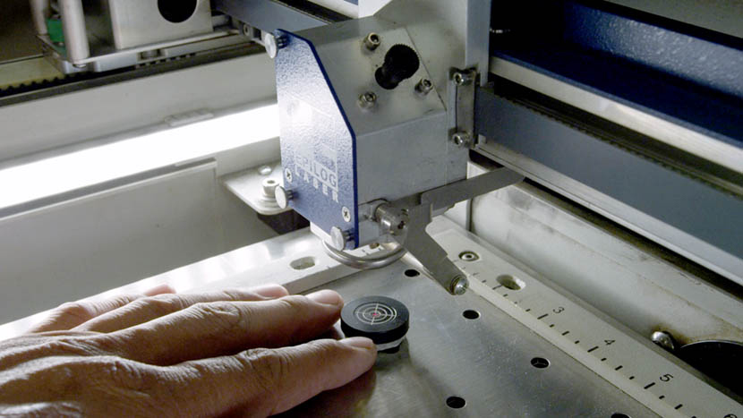
Place the alignment target in the round opening on the side of the lens assembly.
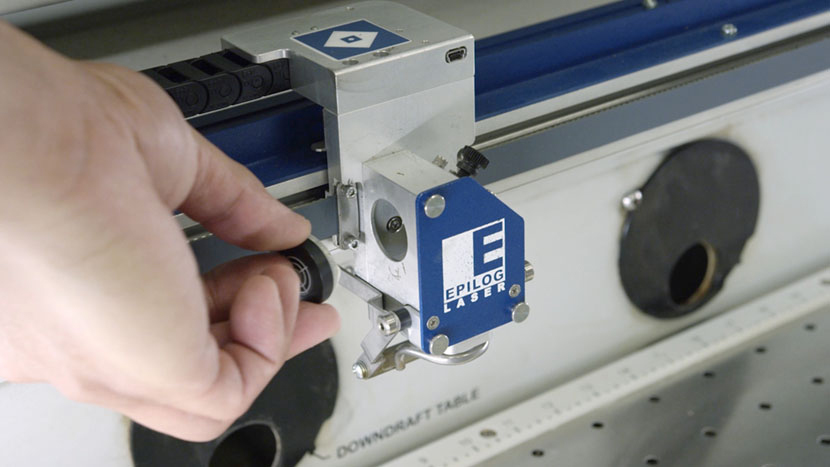
Then cover the alignment target with a small piece of masking tape.
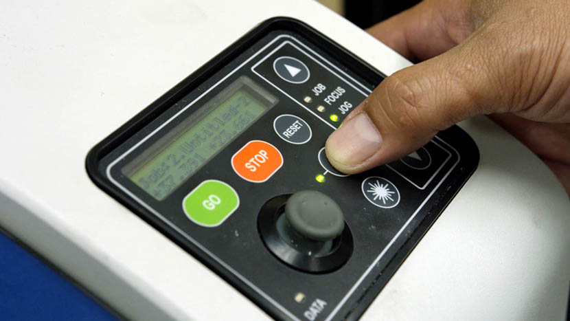
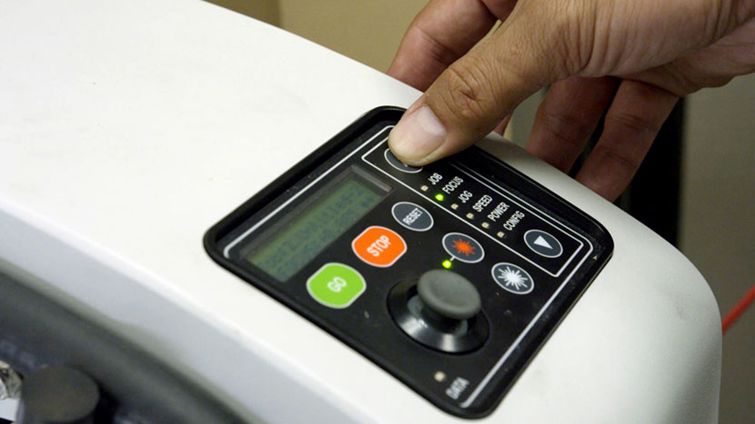
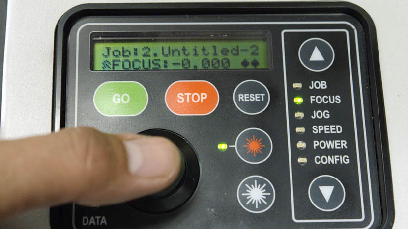
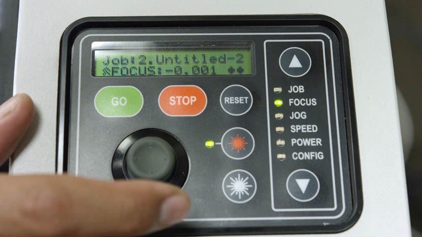
On the control panel, use the arrow buttons to select ‘Jog.’
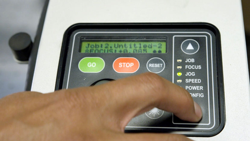
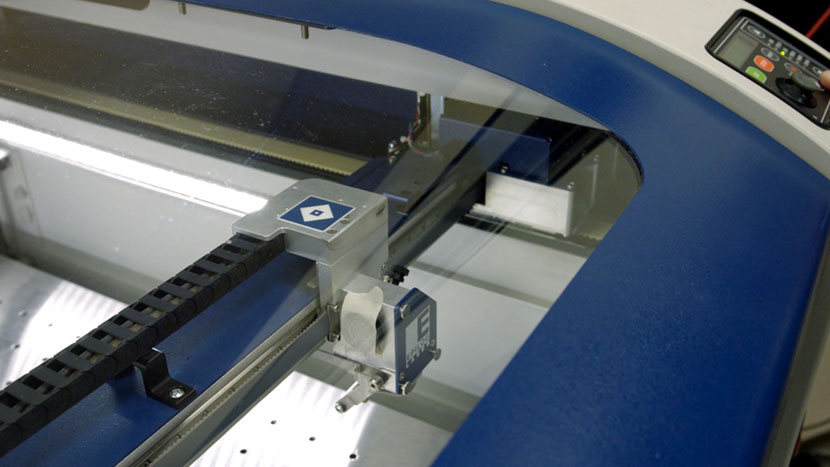
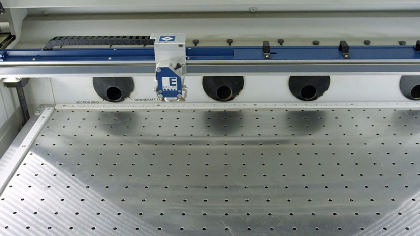
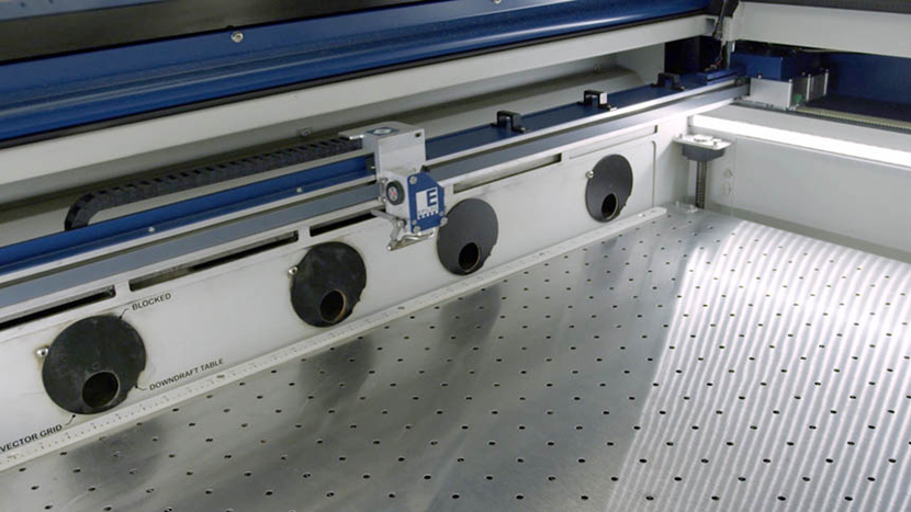
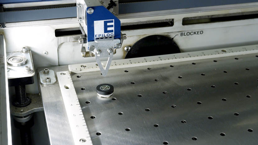
Then use the joystick to move the lens carriage to the front right corner of the machine.
Close the machine’s lid.
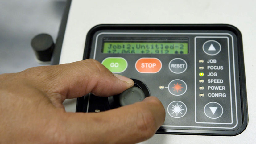
On the control panel, press and hold the “Laser On” button and tap the joystick to the left or right once or twice to fire the laser.
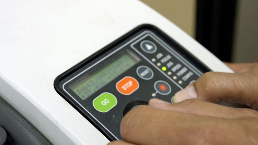
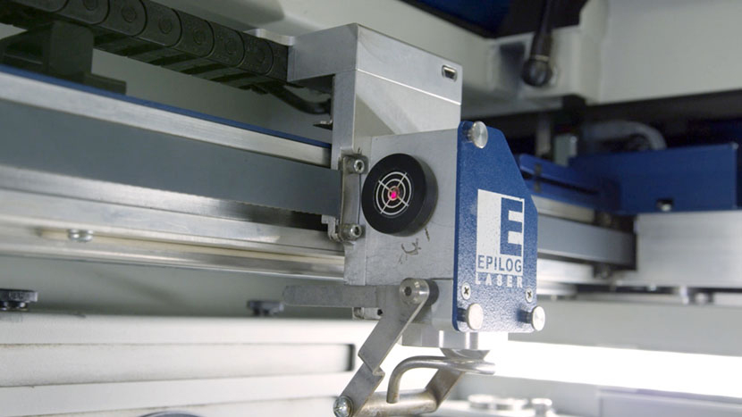
Then press the “Red Dot Pointer” button.
Align Red Dot to Laser
We’ll begin by aligning the red dot laser to the main laser.
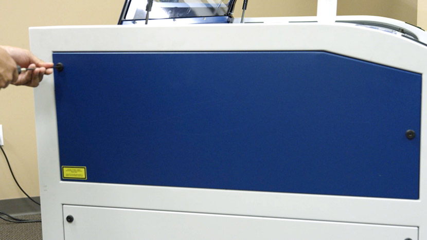
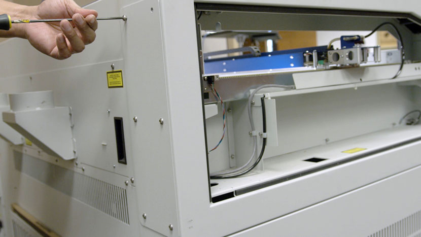
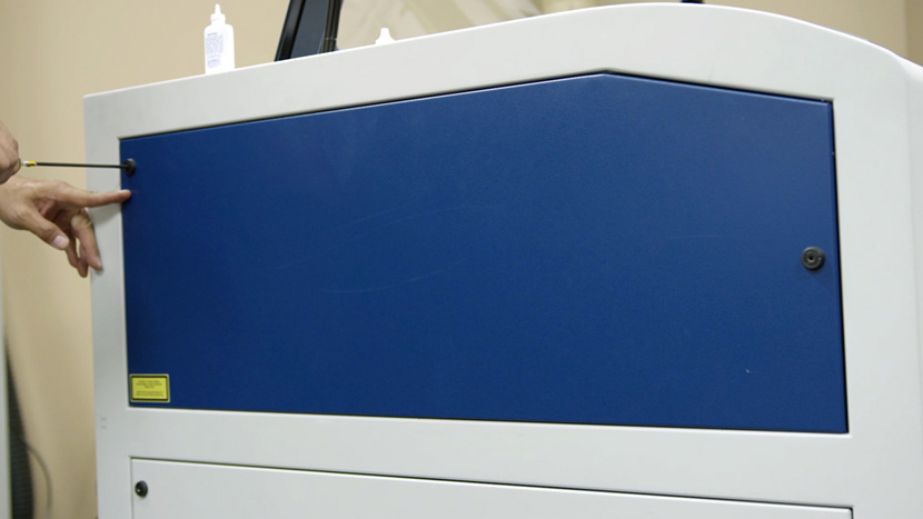
Remove the top access panel on the left side of the machine by using a 5/32” hex key to turn the black panel locks ¾ of the way counter-clockwise.
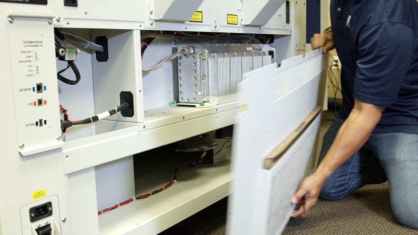
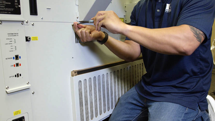
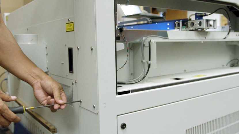
Use a 5/32” hex key to remove the bottom main panel and the top right panel on the back of the machine.
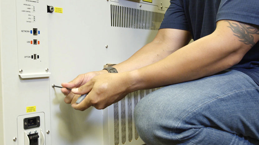
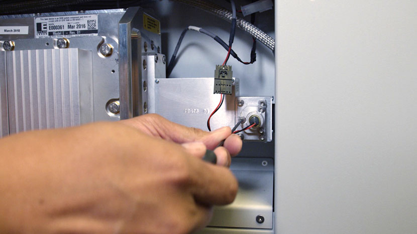
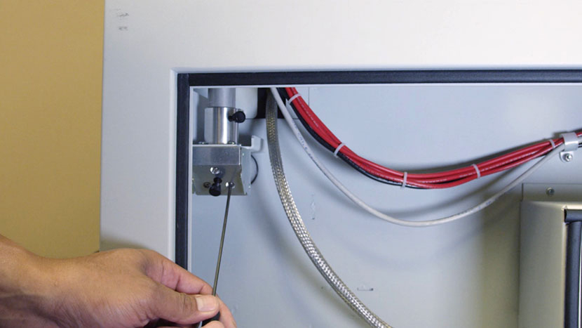
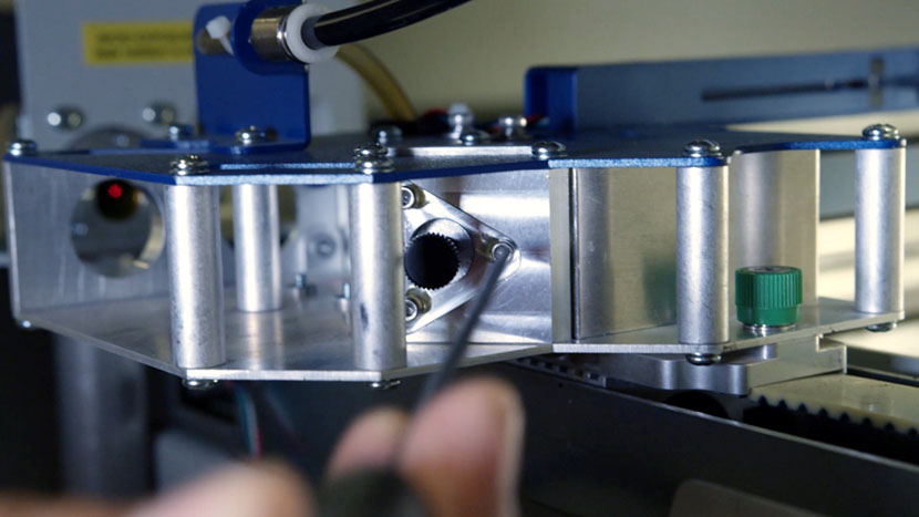
Locate the red dot pointer mount in the rear of the machine. Use a 3/32” hex key to adjust the alignment screws on the red dot pointer mount.
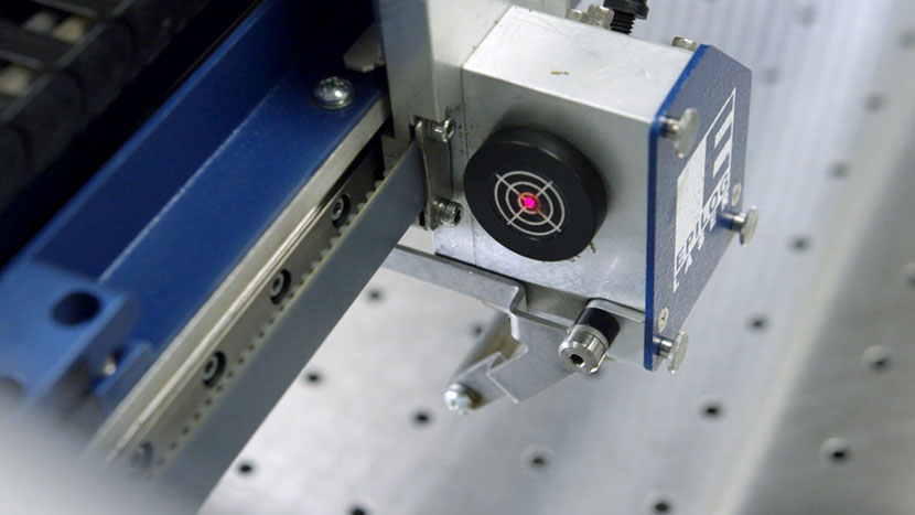
Align the red dot to the burn mark on the alignment target. The two laser beams are now aligned with each other.
Align First Mirror
Remove the tape from the alignment target.
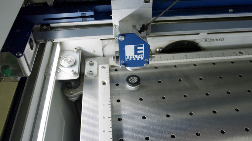
Use the control panel to jog the lens carriage to the back left corner of the machine.
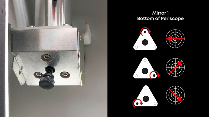
Through the bottom panel on the left side of the machine, use a 3/32” hex key to adjust the alignment screws on the mirror at the bottom of the periscope.
Align the red dot to the center of the alignment target.
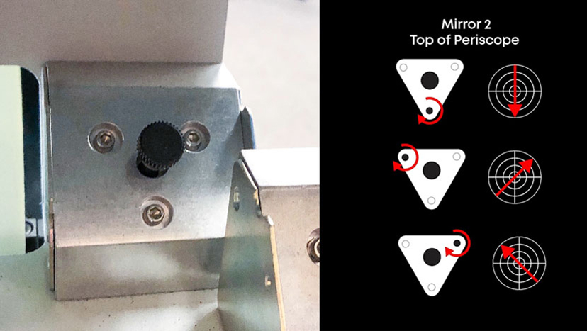
Align Second Mirror
Now jog the lens carriage to the front left corner of the machine.
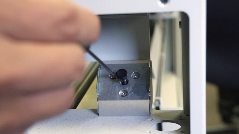
Through the top right corner panel on the back of the machine, use a 3/32” hex key to adjust the alignment screws on the mirror at the top of the periscope.
Align the red dot to the center of the alignment target.
Jog the lens carriage back to the back left corner of the machine and make sure the red dot is still within the center circle of the alignment target.

Align Third Mirror
Now jog the lens carriage to the back right corner of the machine.
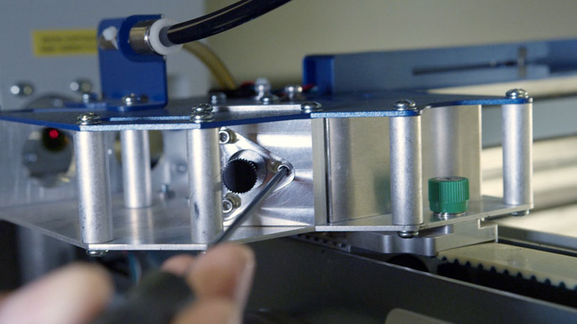
Use a 3/32” hex key to adjust the alignment screws on the mirror at the left end of the x-axis assembly.
Align the red dot to the center of the alignment target.
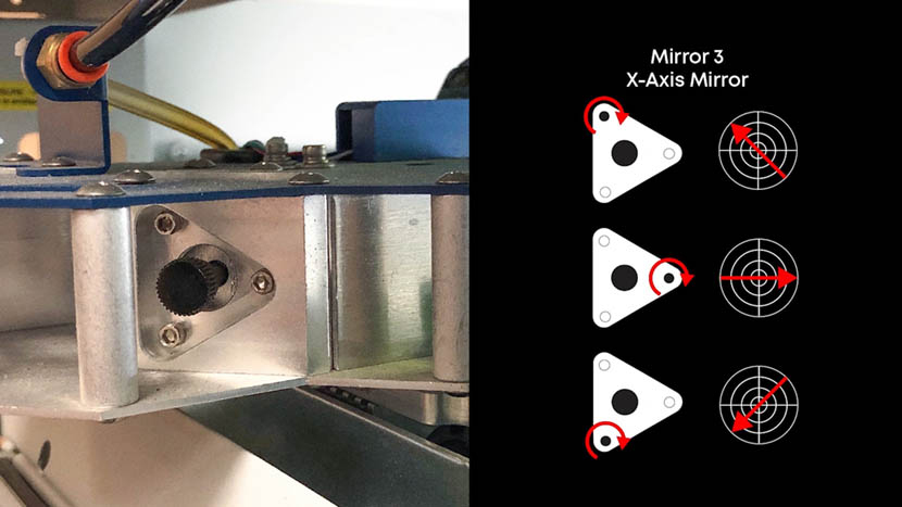
Then jog the lens carriage to the front right corner of the machine.
Use a 3/32” hex key to adjust the alignment screws on the mirror at the left end of the x-axis assembly.
Align the red dot to the center of the alignment target.
Jog the lens carriage to the various corners of the machine and make sure the red dot is still within the center circle of the alignment target at all corners.

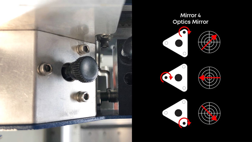
Align Fourth Mirror
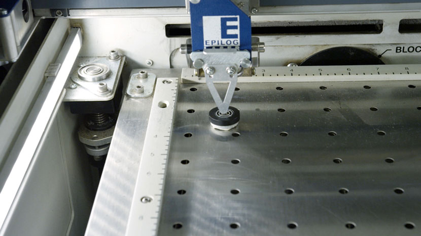
Hang your lens’s focus gauge on the lens assembly and position the alignment target directly beneath the gauge.
On the control panel, use the arrow buttons to select ‘Focus,’ then use the joystick to move the table vertically until the focus gauge just barely touches the alignment target.
On the control panel, press in the joystick once to set this table position as the origin.
Set the focus gauge aside.
With the red dot pointer still turned on, place the alignment target beneath the lens so that the red dot is directly in the center of the target.
With the control panel still set to ‘Focus,’ use the joystick to lower the table until the display reads around +3.000.
Check to see if the red dot has moved out of the center of the alignment target.
If it has, use a 3/32” hex key to adjust the alignment screws on the lens carriage mirror.
Align the red dot to the center of the alignment target.
With the control panel still set to ‘Focus,’ use the joystick to raise the table until the display reads approximately 0.000 again.
Make sure the red dot is still within the center circle of the alignment target.
If the red dot is not properly positioned, continue to adjust the alignment screws until you can lower and raise the table without the red dot leaving the center of the alignment target.
Reinstall Panels
Once the red dot is aligned, use a 5/32” hex key to replace the bottom main panel and the top right panel on the back of the machine.
Replace the top access panel on the left side of the machine by using a 5/32” hex key to turn the black panel locks ¾ of the way clockwise.
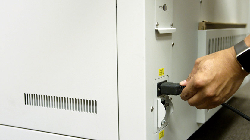
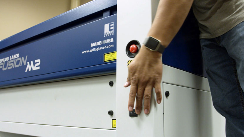
Plug the machine in and turn it on.
Related Articles
17000 (Maker Edge Pro) - CO2 Laser Alignment
Introduction In this article we’ll walk you through aligning the laser on the Epilog Fusion Edge & Fusion Pro. During this procedure, all persons present in the room must be equipped with eye protection, such as safety glasses, eyeglasses or goggles. ...Epilog - Mini, Helix Laser Alignment
CO2 laser alignment should be checked periodically to ensure the engraver is performing optimally. Download the Attached PDF for Detailed Instructions. Complete this procedure if any of the following behaviors are observed: Laser power appears weak ...Epiog - 36 EXT Laser Alignment
CO2 laser alignment should be checked periodically to ensure the engraver is performing optimally. Download the Attached PDF for Detailed Instructions. Complete this procedure if any of the following behaviors are observed: Laser power appears weak ...Epilog - Zing 16 Laser Alignment
CO2 laser alignment should be checked periodically to ensure the engraver is performing optimally. Download the Attached PDF for Detailed Instructions. Complete this procedure if any of the following behaviors are observed: Laser power appears weak ...Epilog - Zing 24 Laser Alignment
CO2 laser alignment should be checked periodically to ensure the engraver is performing optimally. Download the Attached PDF for Detailed Instructions. Complete this procedure if any of the following behaviors are observed: Laser power appears weak ...